Working with 3D Models in Mesh Form
Triangular Mesh
There are many ways to represent 3D models. For example, CSG tree, as in OpenSCAD, or various volumetric octal representations, etc.
However, for 3D printing, boundary representation is most commonly used, specifically triangular mesh (or better in Czech, triangular network). A mesh is a collection of points, edges, and faces (polygons and facets) in three-dimensional Cartesian coordinate system. There are several different types of such mesh; we will deal exclusively with triangular mesh, where a facet can only be a triangle. The advantage of a triangle in 3D space is that three points not lying on one line always form a triangle (4 points don’t have to lie in one plane in three-dimensional space and form a quadrilateral).

Individual facets form a "watertight" boundary between the inside and outside of the 3D model.

Unlike a CSG tree, a mesh is characterized by not carrying information about meaning (it’s not parametric, for example); on the other hand, it’s very fast to render or further process. In the context of OpenSCAD, you can perceive mesh as the result of compilation.
STL Format
Triangular mesh can be stored in various formats. The most widely used format for FDM 3D printing is the STL format (others include OBJ, AMF, 3MF, and more). STL stands for STereoLitography and it’s a format developed by 3D Systems in 1987 as a universal format for rapid prototyping.
Later, meanings of the acronym appeared such as Standard Triangle Language or Standard Tessellation Language.
An STL format file contains a list of triangular facets, their vertices, and normals. There is a human-readable ASCII and more economical binary variant.
The STL format is not an open format, but it’s very widespread, supported by many programs not only from the world of 3D printing.
ASCII STL File
The syntax of a text STL file is quite verbose. It begins with the keyword
solid and the mesh name (which is not often used and is
replaced by the name of the program that was used to generate the file).
Then follows the definition of all facets and the file ends with the directive
endsolid and again the mesh name.
(The file can theoretically contain multiple solid blocks, but in practice
you won’t encounter this often.)
One facet contains information about the normal vector and about three vertices.
solid name

facet normal ni nj nk
    outer loop
        vertex v1x v1y v1z
        vertex v2x v2y v2z
        vertex v3x v3y v3z
    endloop
endfacet

...

endsolid name
The order of facet vertices must follow the right-hand rule: If the thumb points in the direction of the normal (i.e., out of the object), the curled fingers indicate the order of vertices.

Individual numbers can be represented both using floating-point number notation
and "more human" notation; you can encounter values like 1, 0.5, or 2.648000e-002.
Here’s a real example of a cube from OpenSCAD:
solid OpenSCAD_Model
  facet normal -1 0 0
    outer loop
      vertex 0 0 1
      vertex 0 1 1
      vertex 0 0 0
    endloop
  endfacet
...
  facet normal 1 0 0
    outer loop
      vertex 1 0 1
      vertex 1 0 0
      vertex 1 1 1
    endloop
  endfacet
endsolid OpenSCAD_Model
Binary STL
file contains the same information, just in a more economical form. Numbers are
represented by the float32 data type in little endian order.
Viewing STL Files
STL files can be viewed in many programs:
Errors in Triangular Mesh
Even a syntactically completely correct STL file doesn’t have to make sense semantically. Many STL files can contain a number of errors due to various factors. A mesh that contains errors is said to be invalid.
Here we’ll introduce several common errors in STL files:
Open Mesh / Hole in Mesh
The mesh is not "watertight" and contains a hole somewhere.

Often the hole is not caused by a missing facet, but by imprecision in floating-point numbers with low precision.

Duplicate Facet
Multiple facets are located in the same place. Sometimes they’re oriented the same and fully overlap; other times such facets can form part of the model with zero volume.

Incorrectly Oriented Facet
Facet orientation is given by the order of vertices and the normal. This information can contradict each other. Sometimes also part of the 3D model or the entire model is flipped "inside out".

Shared Edge or Face
At first glance an innocent error, but it contradicts the physical representation of the 3D model. Is there a narrow gap between these cubes, or can you pass through a narrow gap from one cube to another?

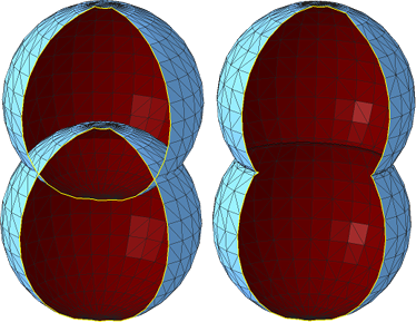
Intersecting Facets
When combining multiple shells, an error often arises where facets intersect each other.
In the image, incorrectly (left) and correctly (right) connected spheres are shown; the hole in the mesh is here only for better view inside.
Repairing Errors in Triangular Mesh
There are many programs that allow repairing the above-mentioned errors. Sometimes these are modeling programs that "additionally" allow detecting such errors and semi-automatically repairing them; sometimes these are specialized programs.
Blender
From the first category we’ll mention Blender, which contains tools for mesh repair and analysis. There’s also an educational DVD for Blender dealing with 3D printing. For FIT CTU students, we have it available.
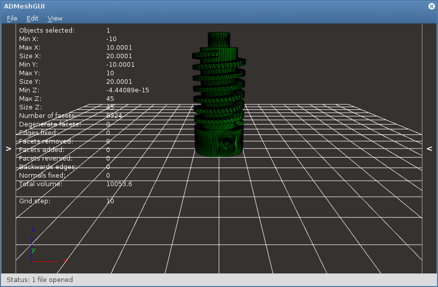
ADMesh
Among programs that try to automatically repair errors in triangular mesh belongs the command line tool ADMesh or the above-mentioned graphical overlay ADMeshGUI. However, the results are not very good.
Netfabb Basic
We have the best experience with mesh repair in the program Netfabb Basic. Unfortunately, this program is not open source and no longer exists.
For Windows, you can use the trial version of the Netfabb program, which after expiration behaves like Netfabb Basic.
For other platforms, you can use our backups of the Netfabb Basic program, which are freely distributable.
We use this program in exercises.
Files
- cube_bad.stl – cube from the video with errors
- cube_correct.stl – cube from the video without errors
- aligator_mini_bad.stl – alligator from the video (original CC BY-SA Joseph Larson)
- bunny_trouble_piece.stl – rabbit from the video (CC BY-NC mrbug)
- tajmahal.stl – ungraded task for practice (CC BY-SA Nicholas Wilson)