Slicing
A 3D printer is ultimately quite a simple device. It doesn’t work as a box to which we send a 3D model in any format and plastic starts flowing from the printer in the shape of the given 3D model. For printing, we need to send precise print data to the printer.
It works similarly as with 2D printers; we also don’t send .pdf or .tex documents directly to the printer, but they must be converted to PostScript. 2D printers are, however, somewhat smarter than 3D printers, since they only need that PostScript data, not direct instructions when and where the printer should move the print head or advance the roller.
Print data for 3D printers are thus precise instructions when, from where, to where, and how fast the printer nozzle should move and at what moment and how much plastic to extrude. The printer listens to these commands and "stupidly" executes them (except for exceptions – some firmwares perform optimization) regardless of whether the printer has any idea what it’s actually printing. We provide such information in the GCode format.
Print data must be prepared for the printer, and it’s a non-trivial task. Successful data preparation defines how successful the print result will be. Many factors are at play that need to be set – speeds, temperatures, correct movements, printing structures that aren’t part of the 3D model, etc.

GCode
GCode is a text file, relatively human-readable (it describes points in space, though, which are hard to imagine from numbers), but primarily intended for machine processing.
GCode existed before 3D printers (the first implementation appeared in the 1950s) and was used for CNC machines (a 3D printer is also by definition a CNC machine). For the purposes of 3D printing, specific codes are added to GCode (starting with M) that define control of functions intended for 3D printing (nozzle temperature, plastic extrusion). These commands may differ for each firmware the printer uses, but slicers can automatically choose the correct ones for the selected printer.
Each line represents an instruction. It’s described by a code stated first (e.g., G1) followed by named arguments by letter (some instructions have no arguments, some arguments are optional) separated by space (e.g., E4.00000 F3000.00000).
...
M900 K200
G21
G90
M83
G1 Z0.200 F10800.000
G1 E-4.00000 F4800.00000
G1 Z0.800 F10800.000
G1 X83.160 Y86.215
G1 Z0.200
G1 E4.00000 F3000.00000
M204 S1000
G1 F1800
G1 X83.537 Y85.576 E0.03743
G1 X83.991 Y85.070 E0.03433
G1 X107.449 Y63.321 E1.61475
G1 X108.199 Y62.760 E0.04729
G1 X108.903 Y62.398 E0.03996
G1 X109.644 Y62.175 E0.03905
G1 X110.427 Y62.102 E0.03971
G1 X142.209 Y63.237 E1.60533
G1 X143.311 Y63.369 E0.05600
...
Tools for Creating GCode
Generating the above-described GCode by hand would not only be impractical, but for more complex models, for the average mortal impossible. Programs called slicers help us create print data. Their name is derived from the word "slice". Because printing is done in layers, the input to these programs is some 3D model and the output is a (sliced) 3D model intended for printing. This is why this process is called "slicing".
There are many slicers; some are better, others worse, some have good UI but don’t do such good work, others are excellent slicers but have terrible UI. Almost all modern maintained slicers have both. A slicer can be standalone software or integrated in some larger whole (e.g., in control software for a 3D printer, a system for controlling a printer farm, a mobile application, or even a web service).
Previously, one of the most popular slicers was Slic3r. However, it stopped being developed and other slicers based on it emerged. The main successors of Slic3r are PrusaSlicer, BambuStudio, and OrcaSlicer. Another popular slicer is Cura by Ultimaker.
In the BI-3DT course we’ll use the program OrcaSlicer. It ranks among the most commonly used, is open-source software, and has many features that allow the user to achieve good output quality even with difficult models. It supports a wide range of printers and is easily configurable.
Slicer Overview and a Bit of History
3D printing has a complex history full of development, innovation, and new ideas. The community around 3D printing tries to share these ideas and various improvements and build on them, which has led to a complex "hierarchy" of slicers.
Slic3r
Slic3r was developed from 2011 to 2018 by the community around the RepRap project. It’s available for all popular operating systems. It was one of the first slicers that had a good user interface, many print settings, and (for its time) good performance. However, its development was discontinued and it was replaced by other slicers. In previous years, this program was used in the teaching of this course.
PrusaSlicer
PrusaSlicer is an open-source slicer based on Slic3r. Its development is mainly driven by Prusa Research, but many other people contribute. It’s suitable for beginners, but has many features that allow advanced users to achieve better results. Prusa Research tries to adapt PrusaSlicer to be as user-friendly as possible, mainly for users of Prusa printers.
BambuStudio
BambuStudio is an open-source slicer based on PrusaSlicer. It’s developed by BambuLab and its goal is user-friendliness and easy configuration for BambuLab printer users. Nowadays it supports other printers too, but development is still focused on BambuLab printer users. It offers a modern user interface suitable for both beginners and advanced users, very good support for printers with multi-color printing capabilities, and other advanced features.
OrcaSlicer
OrcaSlicer is an open-source slicer based on BambuStudio and shares its user interface. It’s developed by the community and its goal is to be a very open and innovative slicer. New (often experimental) features and options are regularly added that allow for better print quality and accuracy.
In exercises we’ll use the OrcaSlicer program, version 2.3.0 or newer.
We’ll import an STL model we want to print into this program, then set (or select) the correct printer configuration (its dimensions and what functions it has) and set print parameters (temperatures, speeds, etc.). The output is a GCode file – print data that can be sent to the printer.

Configuration Files for Printers

Download configuration bundle for the printers we use in this exercise:
Load both files using File → Import → Import Configs. You’ll recognize successful loading by new items in the upper left. You should see Voron 0.2 and Hybrix in the printer selection.
Upozornění:
Setting the correct configuration file is important. Improperly chosen configuration can cause GCode to contain instructions unsuitable for the given printer (e.g., it may start printing too fast/in the wrong place) and such instructions can cause unsuccessful printing, or in the worse case damage the printer. Modern printers usually have some protective features that protect them from damage, but it’s better to avoid these problems.
Důležité:
Before actually preparing print data, we’ll make sure we have the correct configuration files imported in OrcaSlicer. They can be downloaded on this page. Import them into OrcaSlicer using File → Import → Import Configs.
Most of these parameters are set by our configuration files. Nevertheless, we recommend briefly going through these parameters; those interested in examining parameters in detail we’ll refer to the OrcaSlicer wiki.
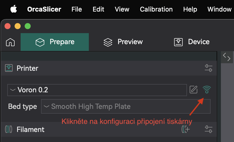
Printer Connection
OrcaSlicer can connect directly to the printer and send gcode for printing over the network. First, open the printer connection configuration by clicking the "WiFi" icon next to the printer name.
In the menu, fill in the printer URL (e.g., voron-02-xx.local) into the Hostname and Device UI fields.

Finally, click the Test button; a dialog should appear confirming that the connection was successful.
Supporting Structures
Besides the 3D model itself that you provide to the slicer, the slicer can add other structures that aren’t in the 3D model. These are structures that help during printing – for better adhesion, for printing overhangs, etc.
Model Interior

In previous exercises you learned that with mesh we describe only the object’s shell, not its interior. Physically on the printer, however, you cannot print only this shell. The slicer takes care of creating the correct object fill. This fill is called "infill".
Objects are commonly not printed hollow (the top of the object would have nothing to print on) nor solid (wasting filament and stress arises in the object that disrupts print integrity). Higher infill density makes the object more resistant, heavier, but also more expensive and takes longer to print. Densities above 70% mostly don’t help print resistance and it’s better to increase the number of walls (perimeters/walls) and reduce infill to a reasonable value. Low density can conversely cause an unsightly print (the object’s shell can sag in some places). In practice, infill is not set to a value lower than 10% nor higher than 50% for a general object. However, there are shapes that can be printed hollow or with very small infill.
Supports (supports)

It often happens that we need to print a model with overhangs. For obvious physical reasons, such printing on FDM printers is not possible (the printer would be printing into air).
Often these problems can be solved by rotating the model or dividing it into multiple parts and subsequent manual gluing after finishing the print. Sometimes such modifications are not possible or desirable, and so the slicer can add supporting structures to our model that are broken off, cut off, or otherwise removed after finishing the print. These supports can either be created automatically, or the user can choose (paint) where exactly they want them.
There are two main types of supports:
Standard Supports

Standard supports are suitable for models that have larger overhangs with simpler shapes. They’re faster to print than tree supports, but use more material and can be harder to remove. They’re not suitable for very detailed models (like the one in the image).
Tree Supports

Tree supports are suitable for models that have many small overhangs that wouldn’t otherwise print. They’re more efficient than standard supports, but can be harder and slower to print. They can hold important areas without unnecessarily touching other parts of the model (which means they leave fewer print defects).
Rafts, skirts, brims
Certain types of prints have problems with adhesion to the print bed surface. During printing they can then detach and at that moment the print becomes unsuccessful.

Problematic are primarily such models that have too small a contact area with the print bed and the area holding the object is too small (imagine for example a table model that we start printing from the legs – the entire object is held only by four small squares).
- Raft
- A structure placed under the print improving adhesion to the print bed. Rafts are rarely used nowadays because modern print beds have good adhesion and printers have more precise calibration. However, they’re still needed in rare cases, e.g., for models that have too small a contact area with the print bed. They create a much larger adhesive base for them that won’t warp or tend to detach/stick to the nozzle during printing. A raft is created by moving the object several layers upward (into air) and underpinning the object with support.
- Skirt
- An outline structure ensuring stable plastic flow during the first layers of printing. It’s printed before the first layer of the object and thanks to this, all air bubbles are extruded from the nozzle and plastic flow stabilizes. Some slicers use other structures for these purposes (e.g., PrusaSlicer, BambuSlicer, and OrcaSlicer make a line at the very edge of the print bed). You can also set a higher number of skirt layers and thus also use it for protecting the print from drafts and subsequent cracking, but in practice this method is rarely used, as it unnecessarily increases material consumption and print time; moreover, it’s very unreliable protection (it’s better to put the printer in a cabinet).
- Brim
- Another structure improving adhesion to the print bed and reducing edge curling. Technically it’s a skirt with zero distance from the model and a height of one layer. It’s not located under the print, but only extends the first layer by a specified size. Brim doesn’t offer as much adhesion improvement as Raft, however, it’s much faster, simpler, unlike Raft doesn’t leave unevenness on the bottom of the model, and for most cases is sufficient. There are several brim variants that differ in shape and model coverage (more information can be found in individual assignments).

| 
|
OrcaSlicer User Interface
Now we’ll move on to what can be set in the OrcaSlicer program and what it’s good for.
Prepare Tab
On the Prepare tab, you work with objects you want to print. With the Add button you can add an STL file. In the 3D preview you can arrange objects across the print bed. With other buttons in the top panel you can manipulate the selected object (rotate with Rotate buttons, or change its size with the Scale button). Additional options like model mirroring are available by right-clicking the model.
On the left side you can select filaments, print profiles, and individual print settings.
Print Settings

Pay the most attention to the Process panel (print settings). While most important values in other panels and tabs were set for you by the configuration files you downloaded above, print settings will be your main task when working in exercises.
Below we’ll list all important parameters you’ll use when printing in exercises. This list is not complete, but if you want to learn something about parameters we don’t mention, we recommend choosing one quiet evening over the OrcaSlicer wiki. Most settings also have inline help that you can display by hovering the mouse over the parameter name (clicking opens the wiki).
Quality Page
- Layer height
- Affects layer height – directly affects quality and print duration. The range of sensible values is affected by the nozzle diameter installed on the printer. It’s recommended not to exceed 75% of the nozzle diameter (in most cases 0.4mm, so the maximum would be 0.3mm).
- First layer height
- Affects the first layer height. Can be set to a smaller or larger value than the rest of the model for better adhesion to the print bed, but is mostly not used. It was previously used to compensate for printer calibration errors.


Strength Page
On this page you can set infill properties, which we know from the chapter Model Interior.
- Wall loops
- Number of perimeters (walls) on print edges (doesn’t affect flat surfaces on the bottom and top of the object).
- Top shell layers and Bottom shell layers
- Number of layers with full fill on bottom and top. The more layers we choose, the stronger the top and bottom surface will be and the better we’ll manage to cover the set infill. High numbers, however, increase print time and material consumption.
- Sparse infill density
- Determines internal fill density.
- Sparse infill pattern
- Determines fill pattern.
- Top surface pattern
- Determines fill pattern on top and bottom external surfaces.
- Solid infill every
- Strengthens object resistance by printing full fill (100%) every n layers.
- Sparse infill direction
- Fill pattern angle.

Speed Page
- NOTE
- Values on this page depend heavily on the model and printer tuning. Faster printing isn’t necessarily better; in certain cases it can negatively affect quality, durability, and reliability of the print. A good rule: it’s faster to print an item once slowly than too fast and having to repeat the print due to problems. Achievable speed is also affected by many other factors (acceleration, nozzle flow rate, cooling), so the set speeds may not always be reached.
- Outer wall
- Outer perimeter speed, has a big effect on quality. Reasonable values are between 60 and 150mm/s (on our Voron printers we use 120mm/s, on Hybrix 60mm/s).
- Inner wall
- Inner perimeter speed, has less effect on quality but can affect accuracy. Reasonable values are between 80 and 250mm/s (on our Vorons we use 200mm/s).
- Sparse infill
- Infill print speed, doesn’t affect quality, but when printing too fast it can cause "lumps" where infill doesn’t adhere in time and causes worse durability (or even print failure). Reasonable values are between 80 and 300mm/s.
- Top surface
- Top layer print speed, affects quality of horizontal print surfaces. Reasonable values are between 80 and 200mm/s.
- Travel
- Speed of travel moves between print parts, can be set high, doesn’t affect print quality, but can cause "collision" with the print at too high speed. Reasonable values are between 100 and 500mm/s (on our Vorons 350mm/s, on Hybrix 200mm/s).
Support Page
On this page you can set supports or raft.
- Enable support
- Turns on support generation.
- Type
- Determines the type of supports (standard or tree, automatic or manual).
- Threshold angle and Threshold overlap
- Determines the threshold for how steep overhangs you want to generate supports. Can be set in degrees (incline from base, the higher the angle, the more supports) or in percentages (how many percent of the perimeter can the next layer still overhang the layer below it).
- Raft layers
- Determines how many raft layers you want to print under the model.
Other Page
On this page you can set Skirt or Brim and other structures/effects, for example Fuzzy skin (more in the next exercise).
- Loops
- Number of skirt outlines. For common use for cleaning the nozzle before printing the first layer, in most cases one or two suffice.
- Distance from object
- Distance of skirt from object.
- Skirt height
- How many layers the skirt will be high. For cleaning the nozzle, usually only one is used.
- Exterior brim width
- Non-zero value will generate a brim around the object of specified size.
Other Panels
The Filament panel, as the name suggests, hides settings related to filament. The most important items are Diameter (determining string diameter, usually 1.75mm) and temperature settings, which differ by material (as you’ll learn in the first printing exercise). On the Cooling page you can then define fan behavior for additional print cooling.
The Printer panel serves for setting printer parameters (size and shape of print bed, number of extruders, maximum speeds, etc.). While items on the Process and Filament panels you change practically with every print, items on this panel mostly remain untouched until you change printer configuration.
Most of these parameters are set by our configuration files. Nevertheless, we recommend briefly going through these parameters; those interested in examining parameters in detail we’ll again refer to the OrcaSlicer wiki.
Slicing Step by Step
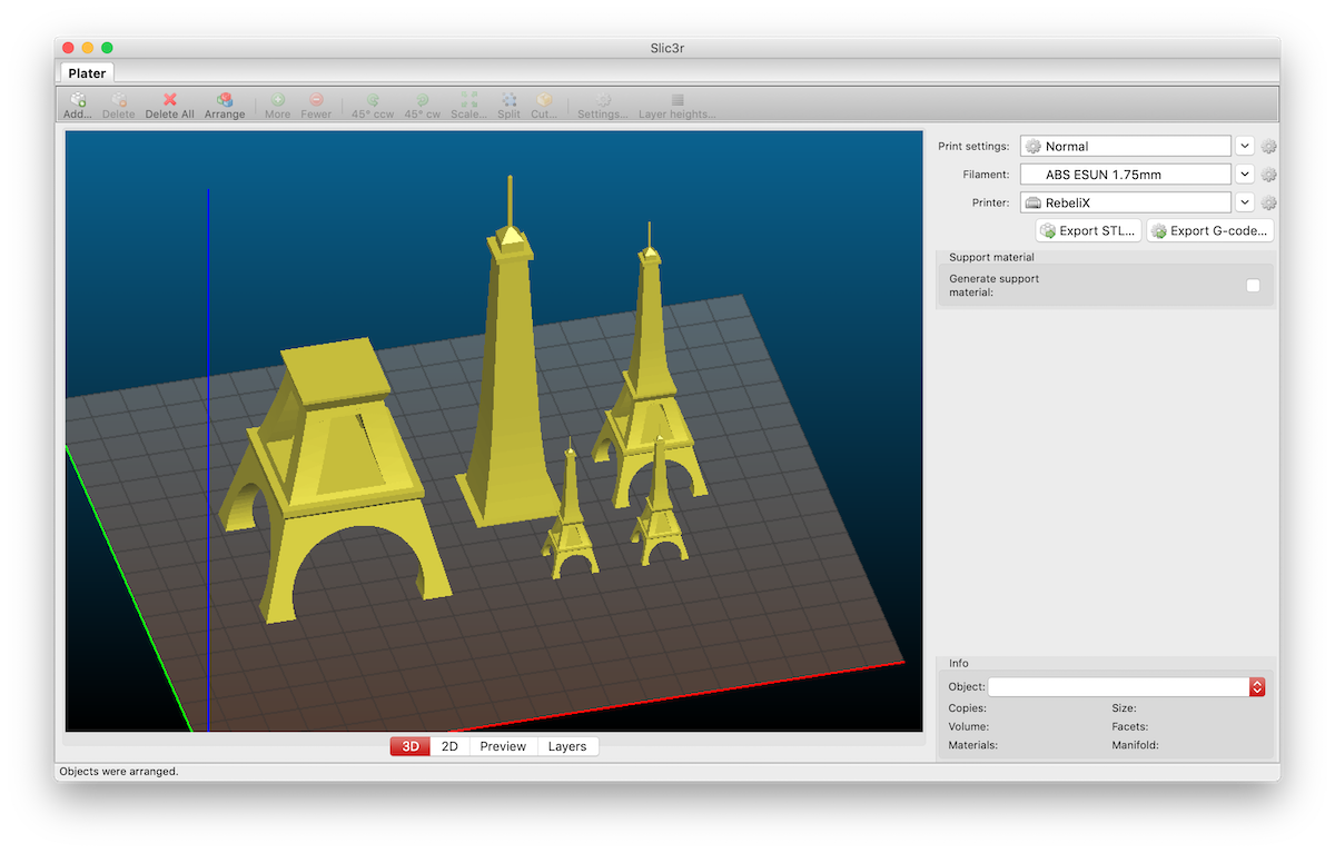
In this chapter we’ll show the entire slicing process on one simple example model. For slicing we’ll use a very simplified model of the Eiffel Tower, which can be safely scaled.
We want to print the model four times: once at double size, once at full size, and twice at half size (1× 200%, 1× 100%, 2× 50%). For the full size, however, we fear that the tower will be taller than the printer can reach, so we’ll divide this variant into two parts and glue it after finishing printing. We’ll consider the print as experimental and so we’ll set parameters so printing is as fast as possible, but at the same time succeeds and the result is at least minimally aesthetic (it shouldn’t be ugly). We fear that the printer won’t handle overhangs at the bottom of the Eiffel Tower, so we’ll add supporting structures. We also have concerns that during printing the legs might detach from the print bed, so we’ll add structures for improving adhesion.
Důležité:
Before actually preparing print data, we’ll make sure we have the correct configuration files imported in OrcaSlicer. They can be downloaded on this page. Import them into OrcaSlicer using File → Import → Import Configs.
Loading Model and Simple Modifications
- On the Prepare tab, using the Add button in the top toolbar, add the STL file to the print bed.
- Right-click on the model and choose Clone from the context menu, which allows you to create copies of the model.
- With the Scale button in the toolbar, set object size to
25 %. This is the object size relative to the original size. So the number states the given size; if we set size to50 %twice, the resulting size won’t be25 %, but still50 %. - With the left button in the 3D preview window, arrange objects as needed. With the Arrange button we can have objects automatically arranged.
- As the last one, duplicate the object (Clone) and perform bisection. The Cut button in the toolbar serves for this. A dialog opens where we set the desired height at which the cut is performed (you can move the cutting plane with the mouse in the object preview using handles). Check both checkboxes Upper part and Lower part, since we want to keep both parts after the cut.
- The result should look similar to the sample screenshot. If we’re satisfied with the print layout, we can move on to setting print parameters.
Setting Print Properties
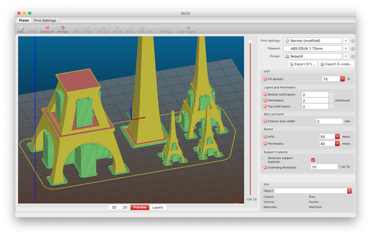
- If you want to display a preview of the prepared print, you can click the Preview button at the top of the OrcaSlicer window. This tab, unlike the Prepare tab, displays additional structures we set in print parameters. We can preview what the final print will look like, even go through it layer by layer (by moving the slider from bottom to top we simulate the print progress). The print settings panel remains on the left side and we can adjust print parameters in it. If we change a setting and the print turns gray and transparent, it means we need to press the Slice plate button in the upper right corner of the window.
- We’ll focus on print parameters. On the Strength panel, set the number of perimeters to
2(item Wall Loops), full layers on bottom and top also to2(items Top Shell Layers and Bottom Shell Layers). Set Sparse infill density to15 %. - On the Others page, arrange for a structure for better adhesion to be printed. Set Brim Type to
Outer brim onlyand Brim width to2 mm. - On the Support page, have supports printed in places where there’s a large overhang. Check the Enable support option. We more or less trust the printer and believe it can handle overhangs from 10° and more. Set Threshold angle to
10°. - On the Speed page, speed up printing at the expense of quality. Increase perimeter print speed by
5 mm/sand infill print speed by10 mm/s. Set Perimeters to40 mm/sand Infill to55 mm/s. - Export the result using the Export G-code file button in the upper right corner of the interface. If instead of the Export G-code file button you see the Print button, you need to click the down arrow next to this button and select Export G-code file.
Credits
Models appeared in images:
- Cute Octopus Says Hello by MakerBot (CC BY 3.0)
- Phone Stand by GoAftens (CC BY 3.0)
- Eiffel Tower by bmfinn (CC BY-SA 3.0)
- Elegant Sea Turtle Sculpture by Oksus (CC BY-NC-ND 4.0)