MeshMixer and Cutting STL Files
You can find the current MeshMixer 3.2 on the program’s website. There are versions for Windows and macOS.
There was an experimental package for Ubuntu 14.04 (you can relatively easily create an AppImage from it and run it on other distributions, or you can take it from the faculty computer).
Video tutorials are created for version 2.9:
Cura is available in two variants, I recommend downloading the older version Cura Lulzbot Edition or older version Ultimaker Cura (15.x) (the new version is completely redesigned and the tutorial won’t match).
This might also be useful:
MeshMixer 2.4
This part of the tutorial (without videos) is for a very old version of MeshMixer, but you can get by with just one program.
Installation
MeshMixer 2.4 can be found on the program’s website.
There are versions for Windows and macOS. In Linux, the Windows version can
be installed using Wine, but you must supply the program folder
(usually ~/.wine/drive_c/Program Files/Autodesk/Meshmixer/) with the files
mfc110u.dll and
prntvpt.dll. The only
problem we’ve encountered is strange fonts and a crash on first launch.
Cutting an Object
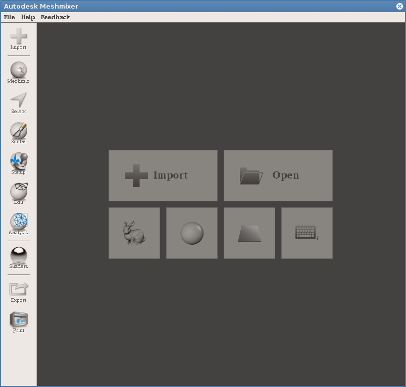
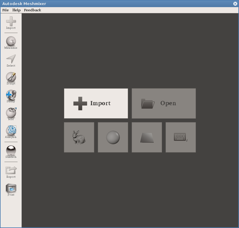
First import the STL file using the Import button.
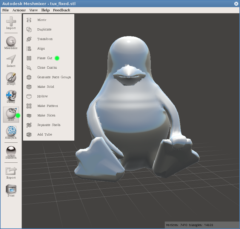
Then select Plane Cut from the Edit menu.
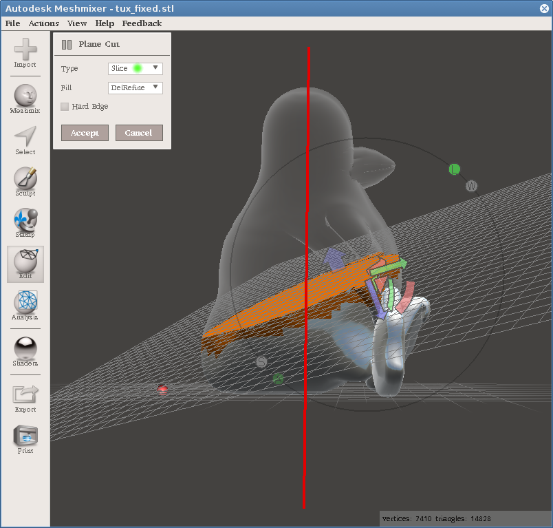
Using various arrows you can manipulate the cutting plane. You can also drag with the mouse button held down to create a line (red in the picture), along which the plane will move, parallel to your view. If the object is positioned unfavorably, you can rotate it with the right mouse button. Before pressing the Accept button, make sure you have selected Type: Slice, otherwise you’ll end up with only one part of the object.
After cutting, the object looks the same as before. You must again select Separate Shells from the Edit menu.
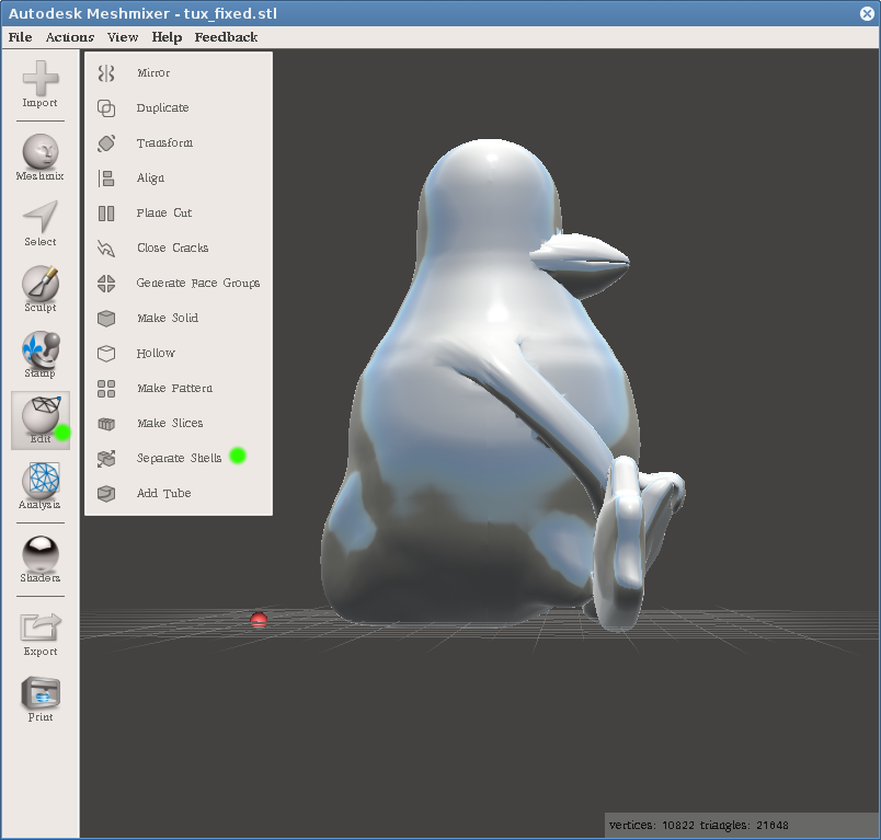
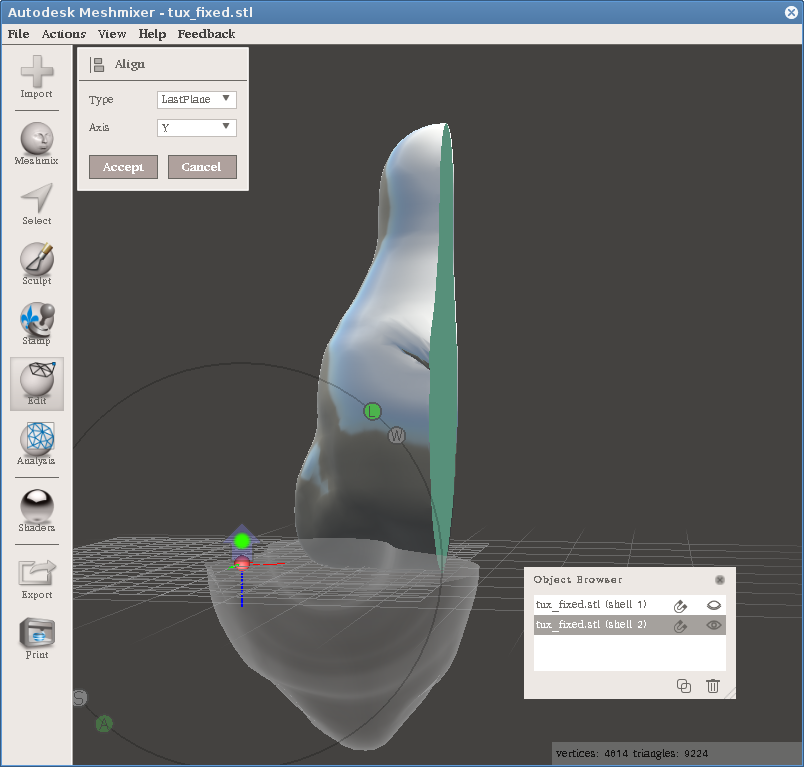
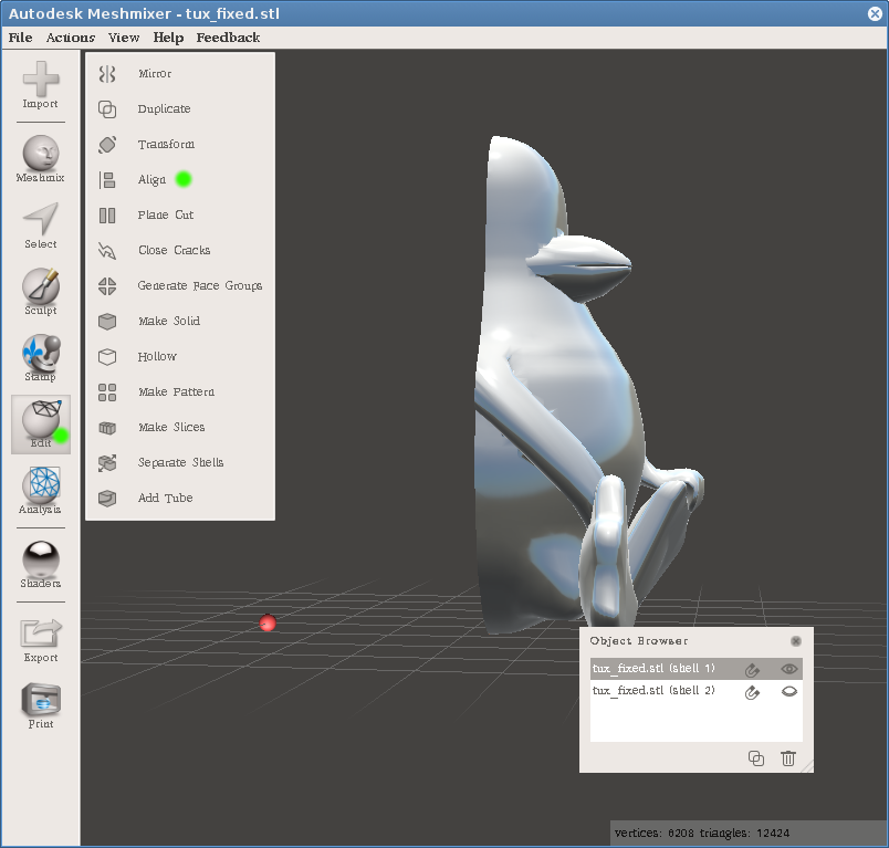
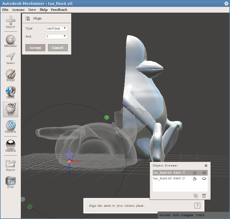
In the modal window you can select which shell will be visible, or on which actions are performed (note, this is different, one is controlled by the eye icon, the other by selecting and highlighting that shell in the list). Immediately for one shell select Align from the Edit menu. This is so that the object lies on a flat part, otherwise the cut was pointless.
In the Align dialog, the Y axis is selected by default. This should ensure laying the object flat (although possibly upside down, we’ll get to that), so just click Accept.
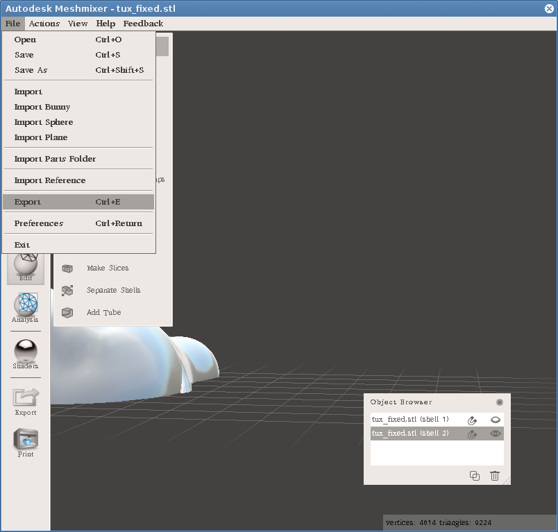
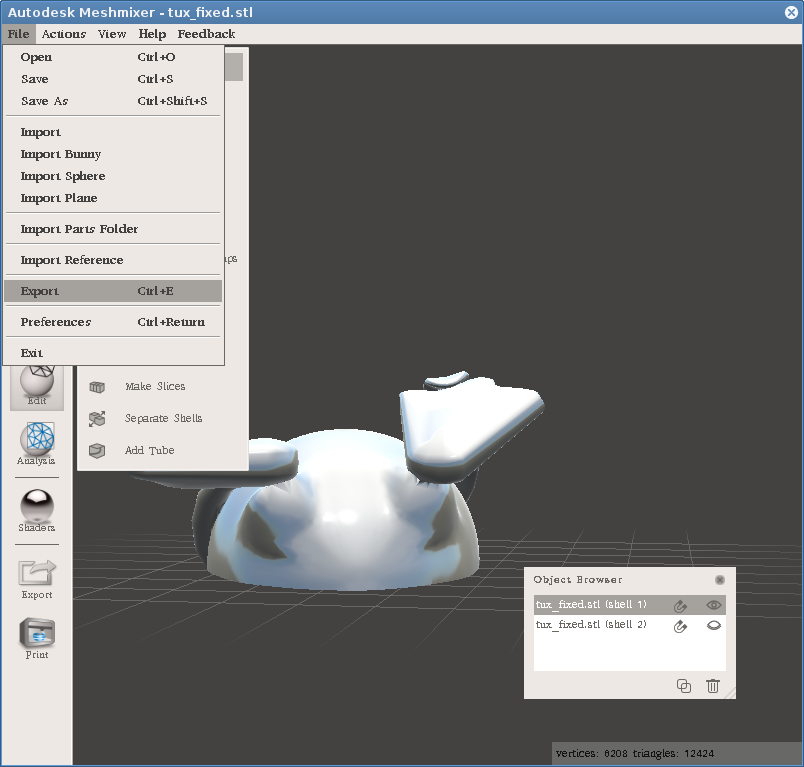
From the File menu, choose Export and save that part as an STL file. I recommend checking that you exported the correct part (by opening the resulting STL in some program).
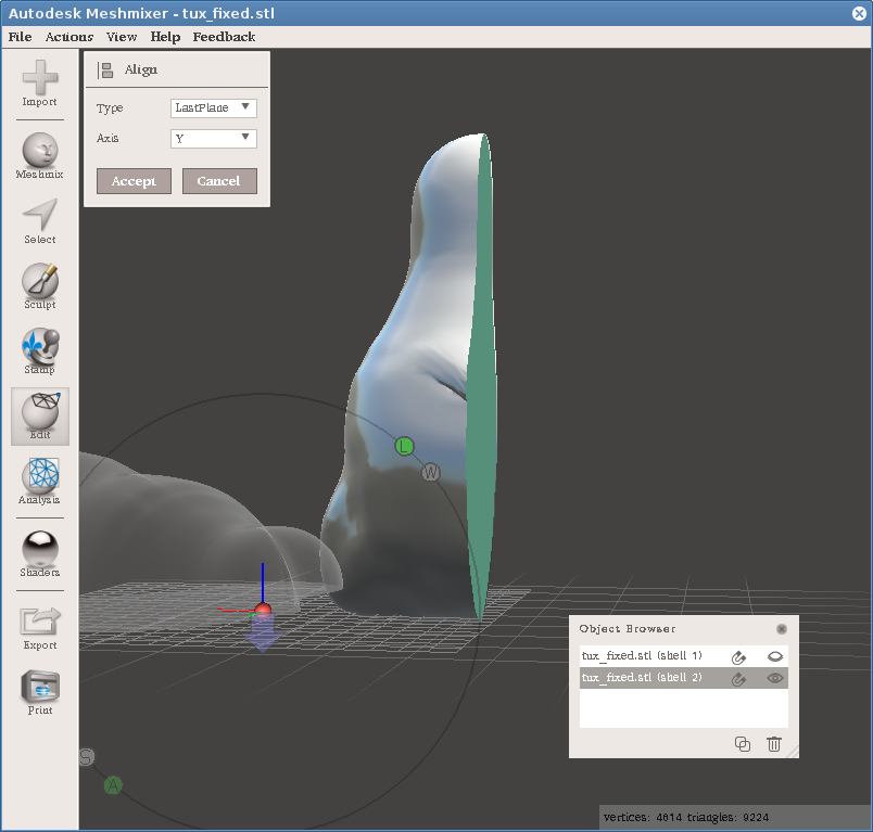
Repeat the process for the second half. Here we encountered a case where Align rotates the object differently than we want. Just click on the arrow (marked with a green dot) and continue as with the previous part.