OpenSCAD
The program OpenSCAD is used for modeling 3D models not only for 3D printers. It’s a program enabling CSG modeling through declarative notation – code.
Use the comprehensive manual in English as a reference.
CSG Modeling
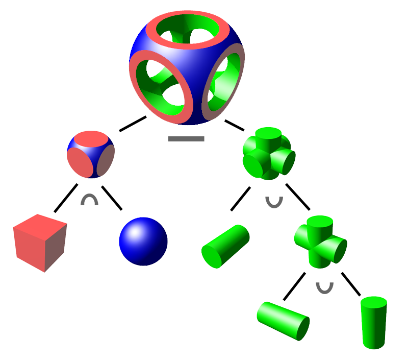
CSG modeling (Constructive Solid Geometry) is vector modeling of graphic elements, in our case 3D models. Basic primitives (sphere, cone/cylinder, cuboid…) are composed into a CSG tree using edges of transformations (translation, scaling, rotation…) and nodes of boolean operations (difference, intersection, union).
In the image you can see an illustration of a CSG tree. Here, for simplification, primitives are already rotated.
OpenSCAD allows writing such trees using code and rendering from them the resulting 3D model in the form of triangular mesh (we’ll learn about that later).
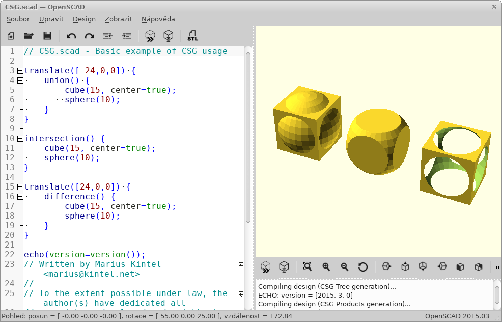
User Interface
The program window consists of three parts:
- Editor
- (left) Here you write the model source code.
- Preview
- (right) 3D canvas where you’ll see the model preview.
- Console
- (right bottom) In the console you can see error and debug output.
After writing code in the editor, you need to "compile" the model. There’s a fast (not always accurate) preview using OpenGL (Design → Display, F5) and a full render to 3D model for export (unfortunately calculated on CPU, Design → Render, F6). In the Design menu you can also enable Automatic Reload and Preview; after saving, the preview is then performed automatically.
In the View menu you’ll find many options for display preview; we recommend enabling axes and scales.
You’ll later use the mouse to navigate the model (try different buttons).
To see anything, however, you need source code. You can choose from a rich selection in File → Examples.
Syntax
The syntax at first glance is very similar to C/C++/Java – it contains semicolons, curly braces, comments are written the same way.
Among other things, you can write numbers
(either whole or with floating decimal point (notation using dot or scientific)) – 1, 0, -5, 5.3, 9.99998, 185e-5;
vectors/coordinates in square brackets – [1, 2, 3]; strings in "double quotes", boolean true/false.
You can use variables (which aren’t declared, but behave non-standardly,
we’ll get to that later), mathematical
expressions
and
functions,
constant PI…
Varování:
Don’t be confused by the syntax; this isn’t a programming language but a descriptive one! This means that individual commands and expressions don’t happen sequentially from top to bottom, but together at once describe the result – the CSG tree.
Primitives
cube(size, center);- cuboid (
size=[1, 2, 3]) or cube (size=5) sphere(r);- sphere (you can use
r– radius ord– diameter) cylinder(…);- (truncated) cone (
h, r1, r2, center) or cylinder (h, r, center) polyhedron(…);- polyhedron, low-level primitive directly describing triangular mesh
cube(150, center=true); 1
sphere(100); 2- centered cube with edge length 150 (notice that arguments can be passed positionally or by name)
- sphere with radius 100
Transformations
Now that you know how to create primitive geometric solids, it’s good to learn to perform individual transformations with them.
scale()- scales object by given constant or vector of three values
resize()- scales object to given size
rotate()- rotates object by angle given in degrees, used as
rotate([deg,deg,deg])orrotate(deg,[1,1,0]) translate([x, y, z])- relative object translation
mirror([x, y, z])- flips (mirrors) object according to plane passing through origin with given normal vector,
e.g.,
[1, 0, 0]mirrors according to YZ plane; mirrored object is not duplicated multmatrix([[…]])- transformation matrix of size 4×4, low-level
color(…)- colors object with given color, only works in preview
Transformations are applied by writing before the object you want to transform:
transformation() object();. They can also be chained; they’re applied sequentially from
"closest" to farthest. They can also be applied to multiple objects at once,
by wrapping objects in curly braces and prefacing them.
transformation() {
  object1();
  object2();
}
Důležité:
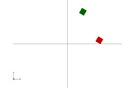
All operations (perhaps except color) happen around the origin. For example, if an object is somewhere away from origin and you rotate it, its position will change.
color("green") rotate([0,0,60]) translate([30,0,0]) cube(5); 1
color("red") translate([30,0,0]) rotate([0,0,60]) cube(5); 2- Cube is first translated, then rotated around origin, and finally colored
- Cube is first rotated around origin, then translated, and finally colored
Boolean Operations
The foundation of CSG modeling are three boolean operations:
union()– union- makes one object from multiple objects (if the resulting CSG tree would have multiple roots, it’s performed on them implicitly)
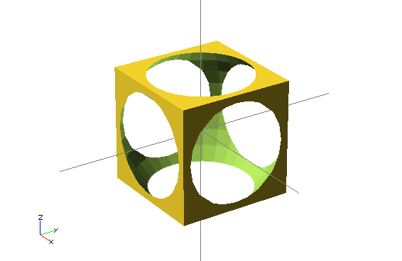
difference()– difference- subtracts all other objects from the first object
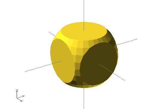
intersection()– intersection- only the common part of all objects remains
union() {
  cube(150, center=true);
  sphere(100);
}difference() {
cube(150, center=true);
sphere(100);
}
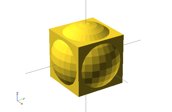
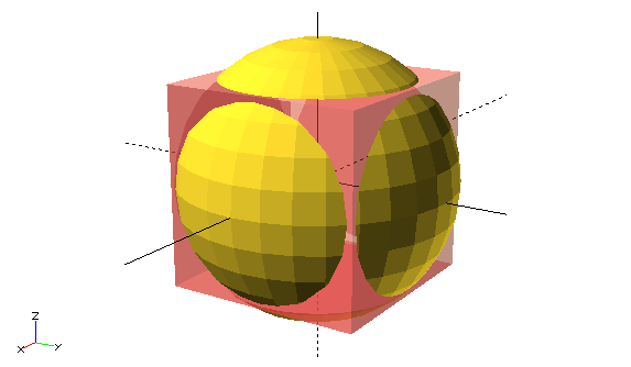
intersection() {
  cube(150, center=true);
  sphere(100);
}
All these operations have no arguments but process any number of objects. Such objects are called children of the given operation. In Czech this means children, but we prefer not to translate this term.
Using Variables
It’s not necessary to use values directly everywhere; in OpenSCAD you can also use variables.
awesome = 42;
cylinder(h=awesome, r=awesome/2);
Keep in mind, however, that everything happens at once. Therefore you can’t redefine a variable; well, you can, but it behaves differently than you’re used to.
awesome = 42;
echo(awesome); 1
awesome = 4242; 2
echo(awesome);- echo function prints debug information to console
- resetting, what happens?
The result is twice printed ECHO: 4242 🤯
The reason is that it doesn’t matter when you set the variable; its value applies throughout the
scope. If you set a variable twice in one scope, the later stated
value applies; take this only as an implementation detail and never do this.
Varování:
For the same reason you can’t use a = a + 1; and syntax for
a += 1; doesn’t even exist (it’s a syntax error).
It helps to think of variables as constants for a given scope. So far we only know one (global) scope, but that will soon change.
Loops
Two or more, use a for.
For syntax is a bit different from C and looks something like this:
for (var = [...]) { 1
    ... 2
}- loop header, we assign a vector to the variable
- in loop body, variable
vartakes values from the used vector
Let’s pause for a moment at vector notation, which can be written in several ways:
- enumeration
var = [-1, 1]– values -1 and 1- interval
var = [0 : 5]– whole numbers from 0 to 5, both bounds are included- interval with step
var = [0 : 0.2 : 5]– values from 0 to 5 (inclusive), step 0.2 is used
We often use this in for loop notation.
for (i = [0:10:100]) echo(i); // => ECHO 10, 20, 30...intersection_for(n = [1 : 6]) {
rotate([0,0,n*60]) translate([5,0,0]) sphere(12);
}
Loops can of course be nested; there’s even a shortcut for this.
for (xpos=[0:3]) {
  for (ypos=[2,4,6]) { 1
    ...
  }
}

for (xpos=[0:3], ypos=[2,4,6]) { 2
  ...
}
- Nested loop
- Shortcut (syntactic sugar) for nested loop
Given how the for loop works in OpenSCAD, here we highlight several pieces of information that the attentive reader has surely already figured out:
- Each "iteration" of the loop has its own scope; any variable settings in the next iteration (and also after loop completion) become invalid.
- From the previous point it follows that you can’t iteratively calculate anything in a loop; it’s only possible to use mathematical expressions with the control variable.
- The while loop doesn’t make sense in OpenSCAD and therefore doesn’t exist.
Conditionals
OpenSCAD contains two types of conditionals: if and ternary operator.
if, else if, else
The if conditional syntax is not surprising (curly braces are optional):
if (...) { 1
  ... 2
} else if (...) { 3
  ... 4
} else { 5
  ... 6
}- boolean expression (e.g.,
a > b,0,true,len(vec) != 42) - own scope!
- optional branch with another condition
- own scope!
- optional branch when no condition holds
- own scope!
Individual branches of the conditional have their own scope. This means that the following code may have a surprising result for someone:
num = 42;

if (num > 0) {
  sign = 1;
} else if (num < 0) {
  sign = -1;
} else {
  sign = 0;
}

echo(sign); // WARNING: Ignoring unknown variable 'sign'.
This feature of OpenSCAD can only be circumvented with the ternary operator.
Ternary Operator
The ternary operator is the only way to conditionally set some value with long-term validity.
num = 42;

// var =   test ? TrueValue : FalseValue;

sign = num > 0 ? 1 : (num < 0 ? -1 : 0); 1
echo(sign); // ECHO: 1- Here we nest operators into each other
Functions
Similarly to the ternary operator, functions are written. Functions don’t create parts of the CSG tree; they only calculate some value from their input. They’re single-expression shortcuts.
function name ( parameters ) = expression;We don’t deal much with functions in this course, but curious students can of course use them. More about functions in the manual.
Modules
The equivalent to a function for the CSG tree is a module. A module is more similar to functions as we know them from programming languages, except it doesn’t return any value but a node (or edge) of the CSG tree.
In layman’s terms: a module "draws" something where it’s used.
Just like a function, a module accepts parameters
that can have default values.
Additionally, it can accept (process) children().
Modules (and functions) can exist in separate files (libraries);
in your own file with a model you can use use or
include:
use <lib.scad>;- makes available modules and functions from file
lib.scad include <lib.scad>;- inserts entire file
lib.scadin place (any objects are immediately rendered)
module rounded_cylinder(h=20, r=5, center=false) {
  baseh = h-2*r;
  translate([0, 0, center ? -baseh/2 : r]) {
    cylinder(h=baseh, r=r);
    sphere(r);
    translate([0, 0, baseh]) sphere(r);
  }
}

// to display you must call the module
rounded_cylinder(center=true);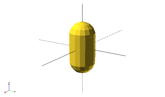
children()
Besides modules that create shapes only based on input parameters
(arguments), you can also create modules that accept children().
This is used for modifying or incorporating any object.
children()- represents all passed objects
children(n)- represents n-th passed object
children([n1, …, nx])- represents n-first through n-x-th passed object
$children- magic (with dollar) constant with number of passed objects
children([1 : 2 : $children])- every second passed object
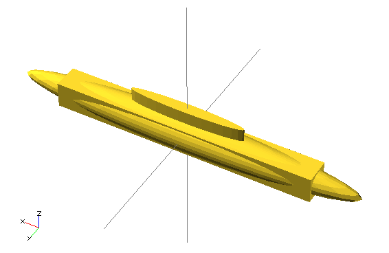
children()module elongate() {
scale([10 , 1, 1])
children();
}
elongate() {
sphere(30);
cube(45, center=true);
cylinder(r=10, h=50);
}
elongate() moduleDebugging
For debugging models it’s good to learn several modifiers:
%- F5 renders node translucently, F6 not at all
#- F5 renders node translucently and in red, F6 normally
!- both F5 and F6 show only this node
*- both F5 and F6 will ignore this node
#difference() {
sphere(45);
#cube(65, center=true);
}
#Helpers
Varování:
Here roughly ends the content of the second exercise and continues the content of the third.
Special operations in OpenSCAD are minkowski() and hull().
Using them you can create complex shapes
that would otherwise be very difficult to create.
Minkowski Sum
Minkowski sum is a set operation where all points from one set are added to all points from the second set. The following image best captures this:

You can imagine it by grasping one of the objects at the coordinate origin and driving with it over the surface of the second object, leaving a trail. This is a commutative and associative operation, so it doesn’t matter which object you drive over which. In practice, this operation is usually used with a sphere for rounding, but be careful, the rounded object will enlarge.
minkowski()minkowski() {
cube(300);
sphere(30);
}
minkowski()Varování:
Calculating the Minkowski sum can take very long.
Convex Hull
Convex hull (convex hull) of objects is such smallest convex object that contains all objects in it. Again it’s a commutative and associative set operation.
hull()hull() {
cube(100);
sphere(30);
}
hull()Varování:
Calculating the convex hull can take quite long.
Two-Dimensional Subsystem
So far we’ve only created three-dimensional objects. In OpenSCAD you can also use a two-dimensional subsystem where you work only on one plane.
In the 2D subsystem you can create 2D primitives:
circle(), square() and polygon().
Using linear_extrude() or rotate_extrude() you can create a 3D object from a 2D object.
Conversely, projection() serves for projecting 3D objects to 2D.
When working in the 2D subsystem, you can use everything you already know;
only the API of some operations appropriately changes
(e.g., translate() takes a vector of 2 values, rotate() takes only one angle…).
hull() {
  rotate(45) square([25, 15]);
  translate([12, 7]) circle(7);
}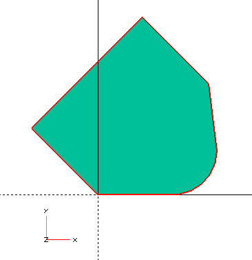
Operations hull() and minkowski() are relatively fast in the 2D subsystem.
So if possible, it’s better to perform them in it.
2D Primitives
square()- alternative to
cube() circle()- alternative to
sphere() polygon()- alternative to
polyhedron()
offset()
For rounding two-dimensional shapes you can use offset().
It has several ways of use:


linear_extrude()
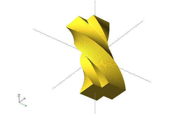
Operation linear_extrude() pulls a 2D shape into space and thus creates a 3D shape.
You can set several parameters:
height- extrusion height
centerfalseextrudes only upward,truein both directions (each by half the height)twist- by how many degrees the 2D shape rotates during extrusion
slices- number of steps for
twist scale- how many times the 2D shape enlarges during extrusion
convexity- value affecting preview; chef advises: "if you don’t know, put 10"
linear_extrude()linear_extrude(height=20, twist=180, slices=100, center=true) {
square(5);
square(5, center=true);
}
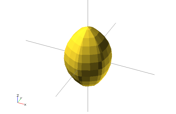
linear_extrude()rotate_extrude()
Another way to convert a 2D shape to a 3D shape is to rotate it.
For this serves rotate_extrude(), which rotates a 2D shape into space.
Rotation happens around the Y axis, but the object "stands up" around the Z axis (we still don’t know why).
rotate_extrude()rotate_extrude()
polygon(points=[[0,0],[20,10],[10,20],[10,30],[30,40],[0,50]]);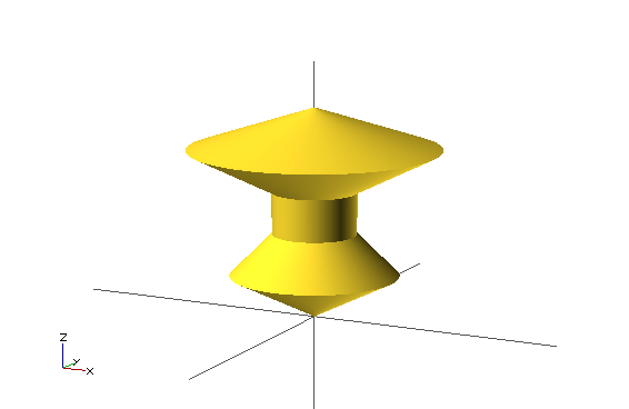
rotate_extrude()projection()
Projection (projection()) projects a 3D object onto the XY plane.
Parameter cut allows using only the intersection with the XY plane.
The result of projection is always a 2D shape;
you can then use it again to create a 3D shape.
projection()projection(cut=true)
translate([0, 0, -15])
rotate([45, 0, 0])
cylinder(r1=0, r2=500, h=500);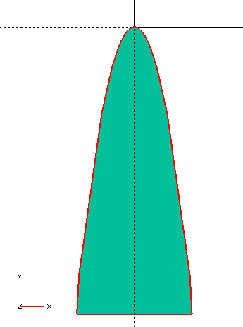
projection()import()
To use already existing 2D or 3D shapes you can use import(),
which allows inserting STL and DXF files into the CSG tree.
The argument is the file path (relative or absolute).
When importing 2D shapes (DXF), pay particular attention to the resulting size;
it’s advisable to use resize().
rotate_extrude()
  resize([20, 0], auto=[false, true])
    import("bottle.dxf");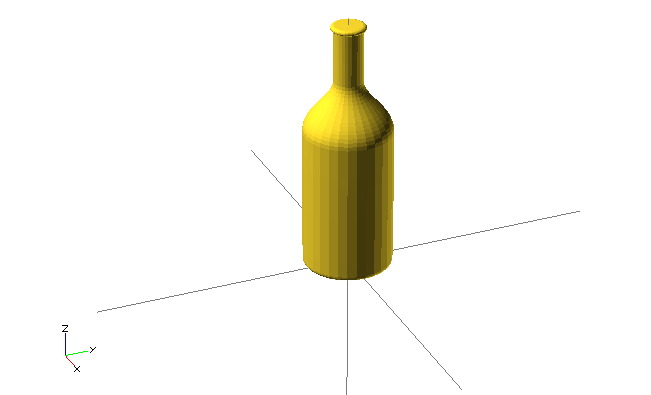
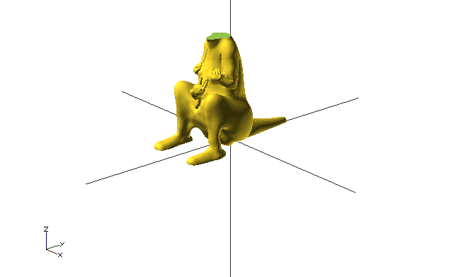
Imported files can be used for any further operations. Foreign STL files don’t always render successfully; they first need to be repaired; we’ll get to that in the exercise about mesh repair.
difference() {
  import("kangaroo.stl"); // http://www.thingiverse.com/thing:33273 CC BY-NC-SA
  translate([0, -10, 80])
    cube(30, center=true);
}
surface()
An alternative way to use external files is surface(),
which serves for converting images to height maps.
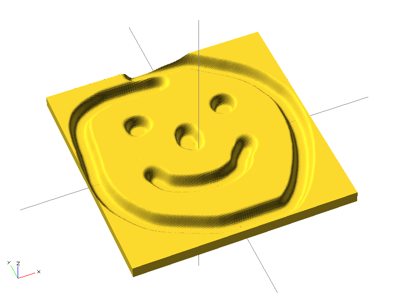
surface(file="smiley.png", center=true); © Torsten Paul (CC BY-SA)
Resolution
You’ve surely noticed that round things in OpenSCAD are angular. The smaller they are, the more noticeable it is.
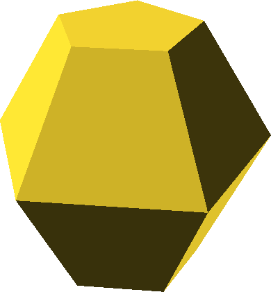
Using special variables $fn, $fa and $fs you can change resolution,
see manual.
In practice, variable $fn is most often set,
which sets the absolute number of edges on a circle (minimum 3).
Shapes are created so that the given size is the size of the circumscribed circle.
Variable $fn can be used, for example, to create an n-gon.
These special variables can be set globally, in scope, or as an argument to any operation, primitive, or module. When creating modules, it’s not necessary to include these variables in the specification.
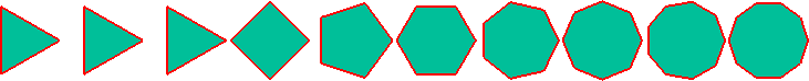
for (fn=[1:10]) translate([fn*2.1,0,0]) circle($fn=fn);Simple – 2-Manifold
For correct STL file export, it’s necessary
for the model to be Simple – 2-Manifold.
This means, among other things, that model walls can’t intersect in all sorts of ways.
Almost all possible problems are solved by the final implicit union().
Some problems can still arise, however,
for example with incorrect use of polyhedron.
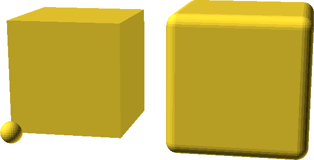
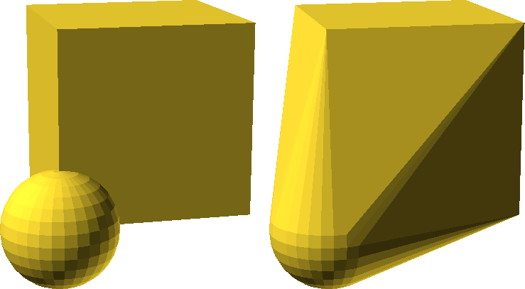
One problem that can arise simply is a shared edge of two objects. If you imagine two cubes (e.g., from the image below), in the real world they can’t have a shared edge. Either you can "pass" from one cube to another, or you can "pass" between them; in other words, either it’s two cubes or one double-cube.
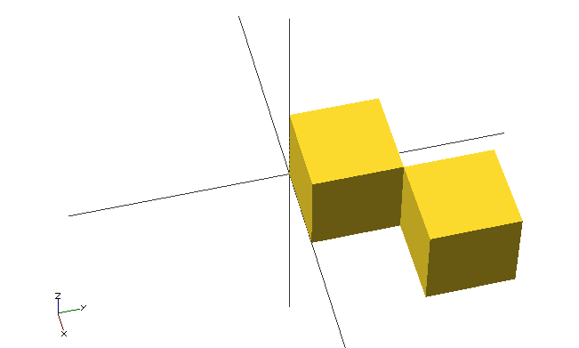
cube(20);
translate([20, 20, 0]) cube(20);e=0.0001;
cube(20);
translate([20-e, 20-e, 0]) cube(20);e=0.0001;
cube(20);
translate([20+e, 20+e, 0]) cube(20);MCAD Library
Using modules you can create various libraries for OpenSCAD. Some already exist; one of them is the MCAD library, which is often distributed together with OpenSCAD.
The MCAD library contains many elementary and advanced things:
- new shapes,
- useful things for RepRap:
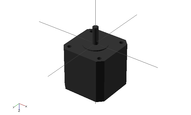
- motors,
- pulleys…
To use the MCAD library you need to use include, not use.
include <MCAD/stepper.scad>
motor(Nema17);